Procedure Development Priorities
Background
The primary goal of air traffic controllers and all published flight procedures is to ensure the safety of operations. Safety is the number one priority for all air traffic control practices and guides all decision making above all else. Safety considerations in designing air traffic procedures include ensuring obstacle clearance from terrain and or man-made objects. The design process in assuring safe obstacle clearance must consider the worst case, an aircraft at its maximum takeoff weight, on a very hot day with one engine inoperative.
All aircraft that will use the procedure must be considered and the poorest climb performer is used to ensure the margin for obstacle clearances can be met. If not the procedure must be redesigned. Another aspect that must be considered is the minimum turn radius, it does no good to design a procedure with a turn segment that is too tight for all aircraft to fly it.
Efficiency in air traffic procedures is the second priority once the safety of flight considerations are resolved satisfactorily. Efficiency is key to ensuring that the national airspace operates smoothly and minimizes ground and airborne delays to users of the system. The primary goal of the FAA's NextGen program is to streamline air traffic management by eliminating current air traffic bottlenecks, reduce aircraft spacing requirements to increase throughput, and shorten the track miles flown to lessen environmental impacts and safe operators money in time and fuel burn.
This is not to say that noise isn't a consideration in the design process but it does have a lower priority than safety and efficiency of the air traffic system. In recent years the FAA has placed considerable emphasis on community involvement and is working in partnership with local airports and surrounding communities to address noise concerns as part of the national air space redesign process.
Performance-Based Navigation (PBN)
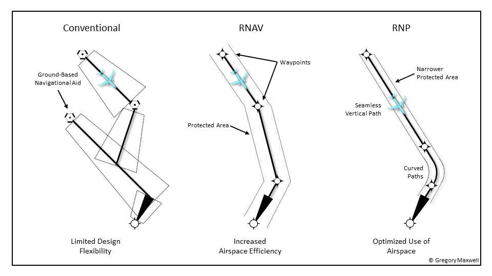
Performance-Based Navigation (PBN) is an advanced, satellite-enabled form of air navigation that creates precise 3-D flight paths and eliminates the need to maintain expensive ground-based navigation aids. More direct flight paths are possible with PBN and airspace bottlenecks can be reduced or even eliminated by removing the reliance on ground-based infrastructure as shown in the graphic below. PBN enables aircraft to fly on any desired flight path within the coverage of ground or satellite-based navigation aides using the aircraft's capability to navigate by means of performance standards utilizing either Area Navigation (RNAV) or Required Navigation Performance (RNP).
PBN specifies that RNP and RNAV systems performance requirements be defined in terms of accuracy, integrity, availability, continuity, and functionality required for the proposed operations in the context of a particular airspace when supported by the appropriate navigation infrastructure. One of the primary goals of PBN is to develop a global standard for RNAV and RNP specifications and eliminate the proliferation of different specifications from country to country.
To use PBN operator's aircraft fleets must meet various avionics equipment standards based on the type of procedure to be flown. Not all aircraft are capable of flying every PBN procedure, and due to the aircraft's age, the cost of equipping them to meet these standards may not be cost-effective.
This concept of air traffic management offers many operational benefits including:
Environmental
- Reduction in emissions by saving fuel, 6.9 lb. of CO2 emissions are eliminated for every 2.2 lb. of fuel savings achieved through shorter and vertically optimized PBN flight paths. In addition, PBN provides a mechanism for optimized profile descents that allow aircraft to descend from cruise altitude to the airport at minimum thrust settings.
- Reduces noise pollution. Consistent precise paths can be routed to avoid noise-sensitive areas. Noise levels can often be reduced through the use of optimized profile descents, which allow lower, quieter thrust levels.
Safety
- Reduces the risk of Controlled Flight Into Terrain (CFIT) accidents by providing a very precise lateral and vertical flight path.
- Provides consistent, predictable, and stabilized approaches. Aircraft arrive at the runway aligned with the centerline, in the same configuration, and at the same speed every time.
- Reduces diversions caused by adverse weather conditions, enabling aircraft to reliably access airports with lower visibility restrictions.
Operations
- Reduces fuel waste through shorter flight tracks, optimized profile descents, and few diversions. Enables more direct and closely spaced parallel tracks en route for increased fuel efficiency and reduced flight time variance. More efficient departure operations enable fuel savings from decreased taxi/ground waiting times.
- Provides a degree of precision approach capability without the investment required for expensive ground-based infrastructure.
- Reduces dependence on radar vectoring, altitude, and speed assignments allowing a reduction in required ATC radio transmissions.
- Creates new market opportunities by providing safe access to terrain and weather challenged destinations. PBN also provides a path for airline growth as emissions caps are implemented around the world.
- Improves customer satisfaction/customer loyalty by allowing airlines to more consistently access airports serviced at higher on-time rates.
Capacity
- Increases traffic capacity through more efficient routes and smoother flows. Reduces airspace conflicts between adjacent airports and prohibited or special use airspace.
Area Navigation (RNAV)
Area Navigation (RNAV) is a method of navigation that permits aircraft operation on any desired flight path within the coverage of ground- or satellite-based navigation aids or within the limits of the capability of self-contained aids, or a combination of these. The major advantage of RNAV is that it allows for very precise continual positioning of the aircraft anywhere on the planet, instead of relying on following defined airways between ground-based navigation aids.
RNAV requires an aircraft to be equipped with a GPS navigation system like a Flight Management System (FMS) which uses the GPS satellite constellation to triangulate the aircraft position within a known fixed radius anywhere on the earth. RNAV is primarily used for departure and arrival procedures that do not require the narrower error tolerance limits defined by RNP procedures.
RNAV includes Performance Based Navigation (PBN) and RNP. The level of precision of RNAV/RNP procedures is expressed based on the navigation precision accuracy required to fly a particular route or procedure as shown in the chart below.
|
RNP Level |
Typical Application |
Primary Route Width (NM) - Centerline to Boundary |
|---|---|---|
|
1 |
Terminal and En Route |
1.0 |
|
2 |
En Route |
2.0 |
|
4 |
Projected for oceanic/remote areas where 30 NM horizontal separation is applied |
4.0 |
|
10 |
Oceanic/remote areas where 50 NM lateral separation is applied |
10.0 |
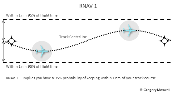
Based on this information, if we have a charted procedure with an RNP level of 1, this means that in order to fly this procedure the aircraft's onboard navigation system must be able to continually calculate it's position within +-1 NM of the track centerline at least 95% of the flight time as illustrated in the graphic below.
The concept of Area Navigation (RNAV) was developed in the 1960s and was an attempt to reduce reliance on ground-based navigation aids (non-directional beacon (NDB), very high-frequency omnidirectional range (VOR), and distance measuring equipment (DME) during the high altitude portion of flight above 18,000 feet. High altitude airways connected the nationwide network of ground-based NAVAIDS. This resulted in inefficient use of airspace and sub-optimal flight routings that were not always very direct costing operators time and money and created bottlenecks in the national airspace system.
In the 1970s to leverage this new RNAV technology, the FAA began to publish RNAV routes for use by appropriately equipped aircraft, mostly commercial airliners. These early routes still relied on signals from ground-based NAVAIDS to calculate the aircraft's position. In total 156 high-altitude RNAV route segments were established by the FAA to enable more direct en-route navigation by aircraft operators.
However, in 1983 the FAA revoked all high altitude RNAV routes in the United States with the exception of Alaska after it learned that operators were using the aircraft's onboard Inertial Navigation System (INS) to navigation point to point, with little utilization of the high-altitude RNAV route network. A subsequent cost-benefit analysis by the FAA indicated there was no justification for sustaining the network when it was being underutilized.
With the deployment of the Global Positioning System (GPS) by the United States Government in 1993, which permitted extremely precise positioning around the globe using satellite-based navigation, the concept of RNAV was revisited by the FAA. In April of 2003, the FAA published 68 FR 16943 which authorized the development of new RNAV routes that were not restricted to ground-based NAVAIDS. The lesser reliance on the costly ground-based NAVAIDS freed up the FAA to develop aircraft routings that were more direct, opened up additional arrival and departure pathways into and out of congested airspace around major hub airports, and provide greater flexibility in airspace management by air traffic controllers.
The FAA and ICAO have published several documents that detail the specifications of RNAV/RNP navigation:
- Aeronautical Information Publication ENR 1.17 Performance-Based Navigation (PBN) and Area Navigation (RNAV)
- Advisory Circular 90-105A - Approval Guidance for RNP Operations and Barometric Vertical Navigation in the U.S. National Airspace System and in Oceanic and Remote Continental Airspace
- Advisory Circular 90-100A - U.S. Terminal and En Route Area Navigation (RNAV) Operations with Change 2
- Advisory Circular 90-101A - Approval Guidance for RNP Procedures with AR
- ICAO Doc 9613, Performance-based Navigation (PBN) Manual
RNAV Procedure Elements
WAYPOINT
A waypoint is a predetermined geographical position that is defined in terms of latitude and longitude coordinates. Waypoints can be named points in space or associated with existing NAVAIDS, intersections, or fixes. A waypoint is most often used to indicate a change in direction, speed, or altitude along the desired path. RNAV procedures make use of both fly-by and fly-over waypoints.
Waypoints naming conventions dictate that each waypoint in the United States Airspace has a unique five-letter code. The waypoint names often reflect people, places, or things of local cultural significance. For instance, there is a SNUPY waypoint near the Sonoma County Airport which is named after Charles M. Schulz the creator of the Peanuts comic strip. Other waypoints are named after local sports teams such as ROKIT in Houston and PISTN in Detroit.
FLY-BY WAYPOINT
A Fly-By waypoint is used to connect two route segments by allowing the aircraft to turn prior to the current waypoint in order to roll out on course to the next waypoint, known as turn anticipation. The aircraft's FMS predicts when to start the turn based on the aircraft's current speed, bank angle, wind velocity, and track angle change to the next waypoint, and calculates a flight path that smoothly transitions from one path segment to the next.
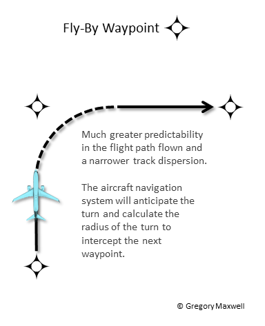
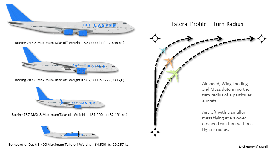
Because the parameters affecting the turn radius can vary from one aircraft to another due to differences in aircraft performance, as well as changing conditions in speed and wind, the turn initiation point and turn area can very as show in the graphic below.
FLY-OVER WAYPOINT
A Fly-Over waypoint is used when the aircraft is required to overfly the waypoint prior to starting a turn to the new course, usually to ensure terrain and or obstacle clearance but in some cases, it can be used for noise abatement purposes. The SPRKY waypoint located 6 miles off the east end of Phoenix Sky Harbor Airport at approximately 4 DME from the PXR VOR is an example of a fly-over waypoint established for noise abatement. All departing jet aircraft are required to overfly this waypoint before turning on course to the next waypoint on their route, subject to ATC exceptions like weather and conflicting traffic.
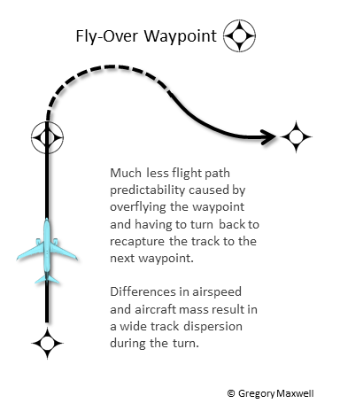
Fly-Over waypoints can result in a great deal of track dispersion in the procedure for the same reasons that affect the turn anticipation of fly-by waypoints. The size of the aircraft (mass), its current airspeed, and the turn radius to intercept the course to the next waypoint on the route will all contribute to the amount of flight track dispersion past the fly-over waypoint.
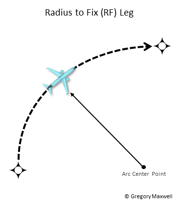
RADIUS TO FIX (RF)
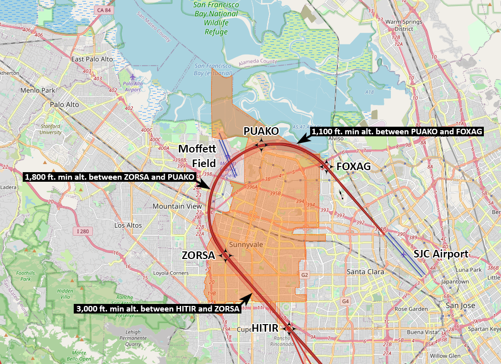
A Radius to Fix (RF) Leg is defined as a constant radius circular path, around a defined turn center point, that starts and terminates at a fix. An RF leg is usually published as part of a terminal or approach procedure. The RNP Z Runway 12R Approach at SJC Airport contains two RF legs between ZORSA->PUAKO and PUAKO->FOXAG. RNP capable aircraft with the onboard navigation equipment required to fly procedures which include RF legs are expected to maintain the same track keeping accuracy during the turn as they would flying a straight line segment. To ensure this procedure designers must take into account bank angle limits for different aircraft types as well as approach speeds and winds aloft.
RNAV Standard Instrument Departure (SID)
An RNAV SID is an FAA published instrument flight rules (IFR) air traffic control (ATC) departure procedure that ensures clearance from obstacles, both natural and man-made, and enables a transition from the terminal control area to the en-route portion of the flight. To date, the FAA has published more than 1,200 RNAV SIDs.
A SID's primary purpose is to expedite traffic flow and reduce pilot/controller workload. They do this by providing fixed paths that guide aircraft along a very precise lateral and vertical path from takeoff to the en-route airspace. These paths minimize level offs to reduce fuel consumption and noise and simplify navigation tasks for pilots and controllers during this high workload portion of the flight.
A SID works much like a freeway on-ramp in helping orderly move aircraft from the terminal airspace onto en-route freeways in the sky. A SID usually includes paths from both runway ends to ensure it can be used regardless of the current air traffic flow direction. Operators choose a particular SID based on the direction of the final destination. SIDs are designed to route aircraft efficiently towards their destination airport. At SJC the majority of traffic is heading to destinations south or east.
SIDs follow the same naming convention as waypoints with five letters, the difference is that the last letter is followed by a number which indicates the current version of the procedure. For example TECKY3 or LOUPE5. Usually, the name of the procedure reflects one of the waypoints on the procedure.
The difference between a SID and an RNAV SID is that RNAV SIDs require as described in the RNAV section that the aircraft's avionics be capable of meeting the performance level of the procedure and specific criteria discussed in Advisory Circular 90-100A. Most RNAV SIDs have a performance level of RNAV 1, meaning the aircraft's navigation system must be able to ensure an error tolerance of no more than 1 NM for 95% of the total flight time. RNAV SIDs are usually flown by the aircraft's autopilot coupled to the flight management system (FMS). RNAV SIDs contain no radar vectors.
In some cases, the FAA has published two similar procedures for the same runways one being a standard SID and the other a more precise RNAV SID. At SJC Airport the LOUPE5 SID and TECKY3 RNAV SID are examples of this concept. Both procedures loop north departures from Runway 30L and 30R back south over the city of San Jose after flying runway heading for approximately 1.8 DME away from the runway end. The difference is the LOUPE5 SID uses headings and an intercept course to a radial of the OAK VOR before turning back towards the airport and receiving radar vectors to proceed on course as described in the chart route description below.
TAKEOFF RUNWAYS 30L/R: Climb heading 306°, at SJC VOR/DME 1.8 DME northwest turn right heading 090° to intercept OAK R-120 to BLNCH, then turn right heading 180° for RADAR vectors to SJC VOR/DME, then on SJC R-340 to BMRNG INT. Maintain 5000, expect filed altitude 10 minutes after departure.
Because the procedure relies on headings which don't account for wind drift and there is much less precision accuracy intercepting and following a VOR radial than a GPS waypoint. As a result the track dispersion can be significant, meaning the flight path is less predictable.
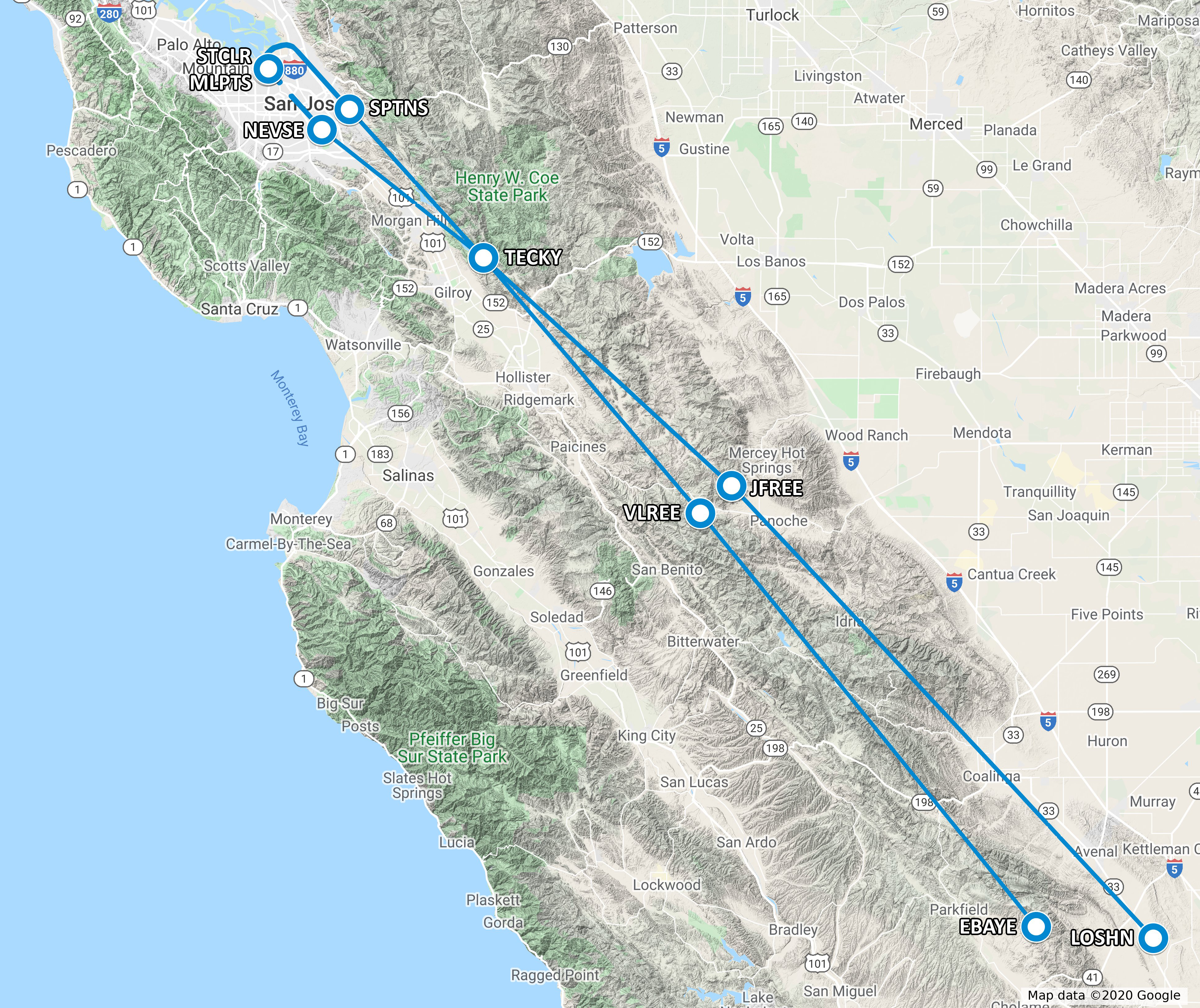
The TECKY3 RNAV SID, on the other hand, uses GPS waypoints instead of compass headings. The procedure as explained in the chart route description below directs departing aircraft from Runway 30L and Runway 30R to separate GPS fly-over waypoints before turning the airplane back towards the airport and then onto one of two paths towards the south.
TAKEOFF RUNWAY 30L: Climb heading 306° to 570, then direct to cross STCLR at or above 900 at or below 230K, then right turn direct to cross SPTNS at 5000, then on track 125° to cross TECKY at or above 13000, thence...
The procedure in addition to directing the aircraft to specific GPS waypoints also includes altitude and speed restrictions which make it much more precise and repeatable from an ATC perspective than the LOUPE5 SID. It also contains guidance from the opposite runway end for departures off Runways 12L and 12R in South Flow, which the LOUPE5 SID doesn't.
RNAV Standard Terminal Arrival Route (STAR)
An RNAV STAR is an FAA published instrument flight rules (IFR) air traffic control (ATC) arrival procedure that ensures clearance from obstacles, terrain and man-made, and enables a transition from the en-route environment to the terminal airspace. STARS may include one or more runway transitions providing guidance to either a standard instrument approach procedure or a point in space from which radar vectors are provided by ATC. To date, the FAA has published more than 860 RNAV STARs.
RNAV STARs are designed like SIDs to provide a precision pathway, with high repeatability that utilizes optimum profile descents (OPD) from top of descent to minimize fuel burn and reduce emissions and noise. STARs often begin over 100 miles or more away from the destination airport. There are usually multiple entry points for a specific STAR to capture arriving traffic from a variety of different directions, like multiple exit ramps off a freeway. The SILCN4 Arrival RNAV STAR illustrated below is designed for traffic arriving from the south.
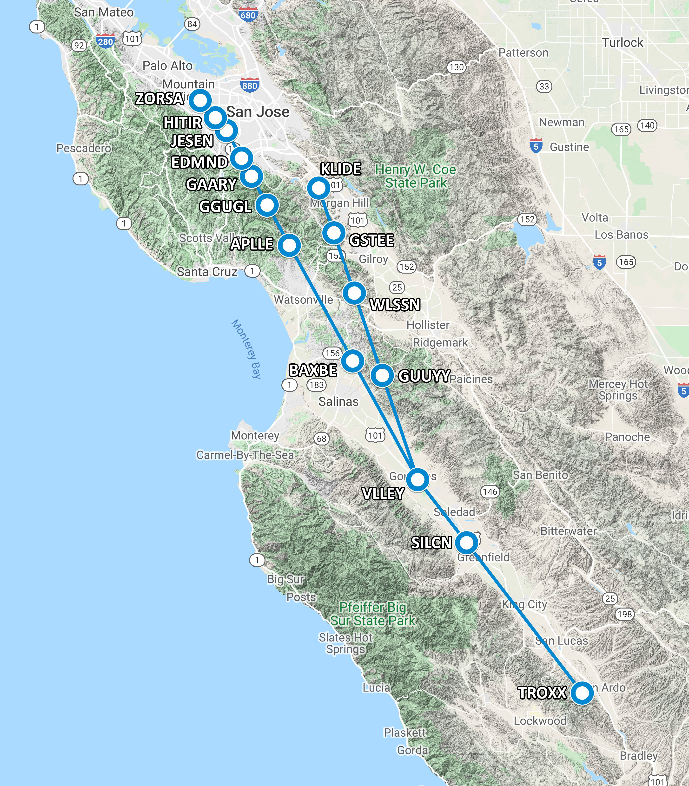
The procedure has two branches to account for the different flow directions (North or South) at SJC Airport. In a North Flow, which the airport operated in approximately 82% of 2019, arriving aircraft on the SILCN4 RNAV STAR landing on Runways 30L/R would fly the west transition from VLLEY to GUUYY->WLSSN->GSTEE->KLIDE. At that point, they are assigned to a landing runway and given radar vectors to join the ILS/LOC or GPS approach to the runway.
When the airport is operating in a South Flow arriving aircraft on the SILCN4 RNAV STAR take the east transition from VLLEY to BAXBE->APLLE->GGUGL->GAARY->EDMND->JESEN->HITIR->ZORSA. If equipped to fly the RNP and cleared by approach control the aircraft would transition at HITIR directly onto the RNP Z Runway 12R Approach. If not equipped or the RNP is unavailable the aircraft would continue towards ZORSA at which point ATC would provide radar vectors and sequencing instructions to direct the aircraft to the final approach to either Runway 12L or 12R.
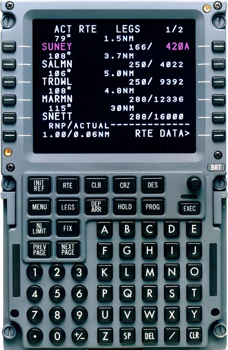
The clearance to fly the RNP Z Runway 12R Approach would probably be issued somewhere between APLLE and GAARY waypoints. However, ATC would instruct the aircrew to expect the RNP Z Runway 12R Approach well in advance of this point to allow the crew sufficient time to brief the approach and set up the procedure in the flight management computer (FMC) to enable the autopilot to fly the aircraft down to the final approach with the runway managing its vertical and lateral navigation. The pilots activate the procedures by selecting it from the procedure list on one of the aircraft's two control display units (CDU) as shown below.
Required Navigation Performance (RNP)
Required Navigation Performance (RNP) is fundamentally similar to RNAV with the difference being that RNP incorporates onboard performance monitoring and alerting (OBPMA). The FMS uses position data from two independent WAAS equipped GPS receivers as well as inertial navigation data to cross-check and monitor the position of the aircraft.
Essentially RNP is a statement of navigation performance necessary for operation within a defined airspace. A cornerstone of RNP is the ability of an aircraft's onboard navigation system to constantly monitor the actual navigation performance, ensuring that the precision level required to fly a certain procedure is being met and alert the pilots at any time the positional calculation accuracy falls below the minimum standard allowed for said procedure. OBPMA ensures predictability and repeatability in flight operations, requiring less direct intervention by air traffic controllers to maintain procedural separation which ensures the safety of operations and increases throughput.
RNP levels are indicated by a number from 0.1-1.0. The number indicates the lateral precision required of the airplane's onboard navigation equipment in order to be authorized to fly the procedure and for the FAA to be assured that the strict lateral containment requirements of a particular procedure can be maintained. This is especially critical in areas where the approach to the airport is highly constrained by terrain (mountains) or other obstacles that leave little lateral safety margin for deviation from the centerline of the procedure.
|
RNP Level |
Typical Application |
Primary Route Width (NM) - Centerline to Boundary |
|---|---|---|
|
0.1 to 1.0 |
RNP AR Approach Segments |
0.1 to 1.0 |
|
0.3 to 1.0 |
RNP Approach Segments |
0.3 to 1.0 |
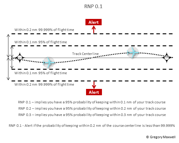
For example, a procedure with an RNP level of 0.1 implies that the aircraft's onboard navigation equipment must be capable of keeping the aircraft within 0.1 NM (608 ft.) of the track centerline for 95% of flight time, and within 0.2 NM of the track centerline 99.999% of flight time. If the aircraft's ability to calculate it's positional accuracy falls below this threshold the aircraft must alert the pilots as illustrated in the graphic below.
RNP capability of an individual aircraft varies based on the aircraft equipment and the navigation infrastructure available. Not all RNP procedures are authorized for every aircraft. The navigation system on a particular airplane will by FAA rules display only procedures for which the specific aircraft is authorized to fly. This means that some procedures may be hidden and unflyable because the airplane's navigation system doesn't meet the RNP requirements necessary to fly the procedure.
RNP Approach
The practical application of RNP was pioneered by Alaska Airlines in 1996 to improve service reliability at some of the world's most remote and terrain challenged airports where weather conditions routinely made it difficult for the carrier to safely and reliably operate. Juneau International Airport served as the proving ground for the airline's RNP efforts. Using a company 737-400 and with assistance from Boeing the team set out to improve reliability and safety of operations at Juneau by leveraging RNP technology.
The team designed, validated, and gained operational approval for an RNP 0.15 approach to Runway 8. The new approach reduced the landing minimums from a 1,000-ft. ceiling and 2 miles of visibility to a 724-ft. ceiling and 1 mile of visibility which greatly enhanced the ability of the airline to operate into Juneau and boosted its flight schedule reliability considerably.
An even greater achievement was developing an RNP 0.3 approach to Runway 26, down the narrow Gastineau Channel which is a narrow fjord with high mountains on each side as shown in the topographic map below.
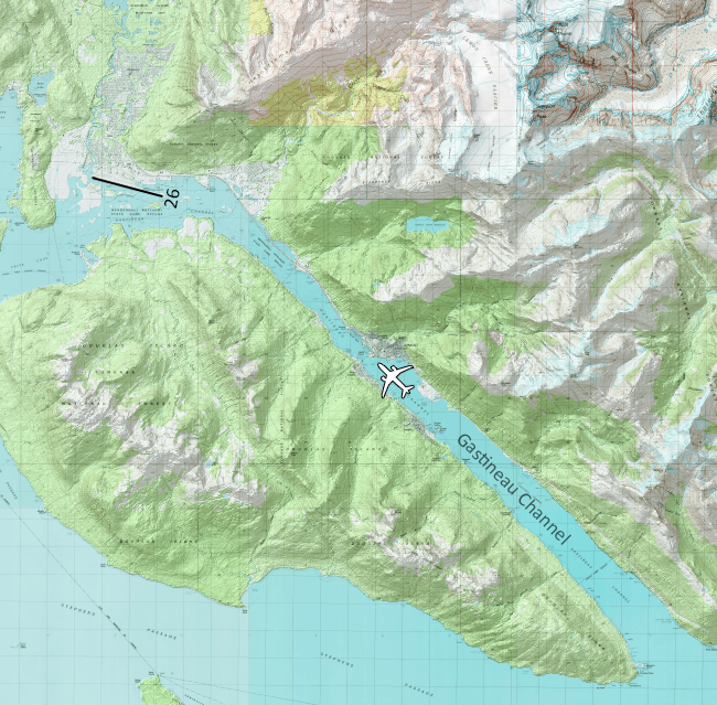
It was the first instrument approach ever developed for Runway 26. It has landing minimums of 337-ft. ceiling and 1-mile visibility. The procedure is proprietary to Alaska, the approach chart isn't publicly available and no other operator can use it. The video below shows the cockpit perspective of the Runway 26 RNP approach into Juneau, Alaska.
There are two different types of RNP approaches. The first is a basic RNP Approach that doesn't require special crew training or onboard navigational equipment. In fact, the only requirement is the aircraft must be fitted with an IFR-approved GPS or GPS enhanced by WAAS.
In the United States, RNP approaches that do not require special equipment or crew qualification are titled RNP previously they were called RNAV (GPS). These approaches offer several different levels of landing minimums to accommodate different degrees of aircraft equipage; either lateral navigation (LNAV), LNAV/vertical navigation (LNAV/VNAV), Localizer Performance with Vertical Guidance (LPV), and Localizer Performance (LP). The ability to fly RF legs is dependent on an individual aircraft's avionics capability.
To date, the FAA has published over 7,000 RNP procedures. Tens of thousands of general aviation aircraft equipped with WAAS utilize more than 3,800 LPV approach procedures at more than 1,880 airports. The vast majority of these airports do not have an instrument landing system (ILS) procedure. The FAA has also published more than 650 localizer performance approach procedures without vertical guidance at more than 490 airports.
SJC Airport has several RNP approaches in place, one such is the RNAV (GPS) Y RWY 12R, which mimics the ILS approach to the runway, but the vertical and horizontal guidance is provided by the aircraft's onboard avionics and the ILS localizer and glideslope is not needed.
RNP Authorization Required Approach (RNP AR)
The second type of RNP approach is an RNP Authorization Required (RNP AR) which was previously known as Special Aircraft and Aircrew Authorization Required or (SAAAR). This type of approach requires much more precise lateral and vertical navigation and involves special aircraft and aircrew certification to fly. To date, the FAA has published almost 400 RNP AR approaches in the United States.
AN RNP AR Approach is defined as an RNP approach procedure that requires lateral total system error (TSE) lower than the standard RNP values on any segment of the approach procedure. RNP approaches include capabilities that require both special aircraft and aircrew authorization similar to a Category II/III ILS operations. All RNP AR approaches have reduced lateral obstacle evaluation areas and vertical obstacle clearance surfaces predicated on the aircraft and aircrew performance requirements. The following specific characteristics differentiate RNP AR approaches from standard RNP approaches:
- Radius to Fix (RF) leg segments may be used after precise final approach fix (PFAF)
- Lateral total system error (TSE) values as low as 0.1 NM on any segment of the approach procedure (initial, intermediate, final or missed)
The main difference between RNP and RNP AR is that the onboard navigation equipment must be able to calculate the aircraft's position with a much smaller rate of error than a standard RNP approach. This requirement is usually driven by obstacle clearance (terrain) considerations, the presence of certain types of Radius to Fix (RF) legs on the approach, or non-standard speeds, or climb gradients during the missed approach segment.
A key focal point of the qualification process of the aircraft is ensuring that no single point of failure can cause the loss of compliance with the RNP guidance tolerances established for the approach. To ensure this aircraft must be equipped with dual GPS (WAAS) sensors, dual flight management systems, dual air data systems, dual autopilot, and a single inertial reference unit.
Individual aircrews can't fly an RNP AR procedure unless they are RNP qualified on the specific aircraft type that will be used to fly the procedure. The RNP AR approval process and the specific requirements that must be demonstrated by an operator are spelled out in FAA Advisory Circular 90-101A Change: 1, and summarized in C384, Required Navigation Performance Procedures with Authorization Required (RNP AR) "RNP AR Compliance Guide."
The greater accuracy in position management required by RNP AR procedures allows ATC to clear an aircraft for the approach with a high degree of certainty of the future track of the aircraft in relation to other airplanes in the airspace. This reduces the controller's workload and requires less direct intervention to manage the aircraft during the approach and landing phases of flight. It also allows ATC to clear an aircraft for an RNP approach with an aircraft simultaneously on an ILS approach to a parallel runway.
As a general rule, only jet and high-performance turboprop aircraft are authorized to fly an RNP AR procedure as the high cost of the specialized onboard navigational equipment and specific crew training and FAA qualification process required makes this type of certification impractical for the average general aviation pilot.
SJC Airport has RNP AR approaches to all four runway ends, but the most impactful to Sunnyvale residents is the RNP Z RWY 12R Approach, which is used during South Flow operations. Additional information concerning South Flow Arrivals can be found on the dedicated SJC South Flow page
image widget